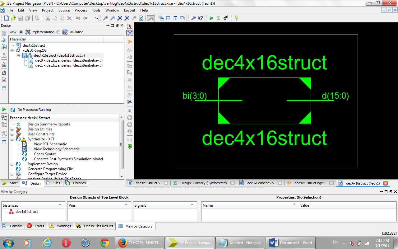
In Verilog Coding, of a particular combinational circuit it is necessary to know the number of input/output a particular chip may require. Since, we now understand the concept behind the decoder, we should start with the logic oriented part. Any digital circuit can be realized using Truth Table.

A decoder is a multiple input, multiple output logic circuit that converts coded inputs into coded outputs where the input and output codes are different. The enable inputs must be ON for the decoder to function, otherwise its outputs assumes a ‘disabled’ output code word. Decoding is necessary in applications such as data multiplexing, seven segment display and memory address decoding.
library ieee;
use ieee.std_logic_1164.all;
- Binary encoder has 2n input lines and n-bit output lines. It can be 4-to-2, 8-to-3 and 16-to-4 line configurations. VHDL Code for 4 to 2 encoder can be designed both in structural and behavioral modelling.
- Write a verilog program for 2 to 4 decoder A decoder is a multiple input, multiple output logic circuit that converts coded inputs into coded outputs where the input and output codes are different. The enable inputs must be ON for the decoder to function, otherwise its outputs assumes a ‘disabled’ output code word.
use ieee.std_logic_arith.all;
use ieee.std_logic_unsigned.all;
module decoder(a, y);
input [1:0] a;
output [3:0] y;
reg [3:0] y;
always @ (a)
case(a)
2’b00: y<= 4’b1110;
2’b01: y<= 4’b1101;
2’b10: y<= 4’b1011;
2’b11: y<= 4’b0111;
end case;
endmodule

Decoder is a digital circuit that can select a line according to the input pattern. Decoder can be used as a control unit for a MCU,processor etc. 4 to 16 line decoder verilog code arr given bellow.
module decoder(x,y,z,w,e,d);
input w,x,y,z,e;
output [15:0]d;
assign d[0]= (~x) & (~y) &(~z) & (~w) & (e) ;
assign d[1]= (~x) & (~y) &(~z) & & (e) ;
assign d[2]= (~x) & (~y) &(z) & (~w) & (e) ;
assign d[3]= (~x) & (~y) &(z) & & (e) ;
assign d[4]= (~x) & (y) &(~z) & (~w) & (e) ;
assign d[5]= (~x) & (y) &(~z) & & (e) ;
assign d[6]= (~x) & (y) &(z) & (~w) & (e) ;
assign d[7]= (~x) & (y) &(z) & & (e) ;
assign d[8]= (x) & (~y) &(~z) & (~w) & (e) ;
assign d[9]= (x) & (~y) &(~z) & & (e) ;
assign d[10]= (x) & (~y) &(z) & (~w) & (e) ;
assign d[11]= (x) & (~y) &(z) & & (e) ;
assign d[12]= (x) & (y) &(~z) & (~w) & (e) ;
assign d[13]= (x) & (y) &(~z) & & (e) ;
assign d[14]= (x) & (y) &(z) & (~w) & (e) ;
assign d[15]= (x) & (y) &(z) & & (e) ;
endmodule

module decoder2();
reg x0,y0,z0,w0,e0;
wire [15:0]dd;
initial
begin
e0=0;
x0=0;
y0=1;
z0=0;
w0=1;
#10 e0=1;
#00 x0=0;
#00 y0=0;
#00 z0=0;
#00 w0=0;

4 To 16 Decoder Using 2 To 4 Decoder Verilog Codes
#10 x0=0;
#00 y0=0;
#00 z0=1;
#00 w0=1;
#10 x0=0;
#00 y0=1;
#00 z0=0;
#00 w0=0;
4 To 16 Decoder Using 2 To 4 Decoder With Enable
#10 e0=0;
end
decoder s(.d(dd),.e(e0),.x(x0),.y(y0),.z(z0),.w(w0));
endmodule